The cmds are listed in alphabetical order with more or less description of
meaning and arguments. But you also find several tables of content. The library
is not yet complete, but hopefully one day it will be. At the end of the text
there is a short tutorial of Nic "Swervin Irvin" Prins about how to deal with
cmds, inserting and removing.
The information is collected from different
sources. In the text i tried to give appropriate credits, and i hope i didnt
forget somebody (sorry in advance!). In order to keep the document as short as
possible i refer to the people with abbreviations. A list of "who is who" can be
found in the appendix.
All mentioned tutorials can be found in the tutorials section of the track
editor homepage. Some of them also can be found on the authors gp2-webpage http://www.asit.ch/~addie/index.html
.
You are all invited to verify, correct and/or extend the descriptions
you find here. If you do, please prooved by examples, so i can verify it
...
And every idea of making this document more usuable is welcome
!
As this is a growing document, you may want to watch the version number
at the top, and the revision history at the end of the file.
Thanks for "beta reading" this version to [alphabetical order]:
Paul
Arnall, Dan Chinnapen, Vaino Iso-Hannula, Paul Hoad, Martijn Keizer, Adalberto
Zapparoli !
Short
List as short as it gets
Long
List cmd-numbers and names
Sorted
List like long-list but grouped by subject
Appendix
Location
Code Tables
Glossary
Notes
for Unk-Chasing
Revision
History
0x80
(128) 0x81
(129) 0x82
(130) 0x83 (131)
0x84
(132) 0x85 (133)
0x86
(134) 0x87
(135)
0x88
(136) 0x89 (137)
0x8a
(138) 0x8b
(139) 0x8c
(140) 0x8d
(141) 0x8e
(142) 0x8f
(143)
0x90
(144) 0x91
(145) 0x92 (146)
0x93
(147) 0x94
(148) 0x95
(149) 0x96
(150) 0x97
(151)
0x98
(152) 0x99
(153) 0x9a (154)
0x9b
(155) 0x9c
(156) 0x9d
(157) 0x9e
(158) 0x9f
(159)
0xa0 (160)
0xa1
(161) 0xa2
(162) 0xa3
(163) 0xa4 (164)
0xa5(165)
0xa6
(166) 0xa7
(167)
0xa8 (168)
0xa9
(169) 0xaa
(170) 0xab
(171) 0xac (172)
0xad
(173) 0xae (174)
0xaf
(175)
0xb0
(176) 0xb1 (177)
0xb2
(178) 0xb3 (179)
0xb4
(180) 0xb5 (181)
0xb6
(182) 0xb7
(183)
0xb8 (184)
0xb9
(185) 0xba
(186) 0xbb
(187) 0xbc (188)
0xbd
(189) 0xbe
(190) 0xbf
(191)
0xc0
(192) 0xc1
(193) 0xc2
(194) 0xc3 (195)
0xc4
(196) 0xc5
(197) 0xc6
(198) 0xc7
(199)
0xc8
(200) 0xc9 (201)
0xca
(202) 0xcb
(203) 0xcc
(204) 0xcd (205)
0xce
(206) 0xcf
(207)
0xd0
(208) 0xd1
(209) 0xd2 (210)
0xd3
(211) 0xd4
(212) 0xd5
(213) 0xd6 (214)
0xd7
(215)
0xd8
(216) 0xd9 (217)
0xda
(218) 0xdb
(219) 0xdc (220)
0xdd
(221) 0xde
(222) 0xdf
(223)
0x80
(128) Object Position
0x81 (129)
View Distance In Front
0x82 (130)
View Distance Behind
0x83 (131)
unk
0x84
(132) unk
0x85
(133) Track Width Change
0x86 (134)
Connect Pit Lane Start
0x87 (135)
Connect Pit Lane End
0x88 (136)
Pit Lane Cmd; Left Pits
0x89 (137)
Pit Lane Cmd; Right Pits
0x8a
(138) Track Markings Type A
0x8b
(139) Track Markings Type B
0x8e (142)
Left Kerbs Begin/Length
0x8c
(140) unk
0x8d
(141) unk
0x8f (143)
Right Kerbs Begin/Length
0x90 (144)
unk
0x91
(145) unk
0x92 (146)
unk
0x93
(147) unk
0x94 (148)
unk
0x95 (149)
unk
0x96
(150) Speed Limiter On
0x97 (151)
Speed Limiter Off
0x98 (152)
Left Fence Height Change
0x99 (153)
Right Fence Height Change
0x9a (154)
Left Fence Height Change
0x9b
(155) Pit Lane Begin Offset
0x9c
(156) unk
0x9d
(157 unk
0x9e (158)
Pit Lane End Length
0x9f (159)
Pit Lane Fences Begin
0xa0 (160)
Pit Lane Fences End
0xa1 (161)
Pit Lane Entry; Join Right Pit Lane Fence
0xa2 (162)
Pit Lane Entry; Join Left Pit Lane Fence
0xa3 (163)
Pit Lane Exit; Join Right Pit Lane Fence
0xa4 (164)
Pit Lane Exit; Join Left Pit Lane Fence
0xa5
(165) unk
0xa6 (166)
unk
0xa7
(167) unk
0xa8 (168)
Trigger Of Flag Men Waving At End Of Race
0xa9 (169)
unk
0xaa
(170) unk
0xab (171)
unk
0xac
(172) unk
0xad (173)
Track Banking
0xae (174)
unk
0xaf
(175) Pair Of Swivel Arms
0xb0 (176)
Turn Ribbons/Banks Off
0xb1 (177)
unk
0xb2
(178) Switch Borderlines On/Off
0xb3 (179)
unk
0xb4
(180) Track Width Change Left
0xb5 (181)
Track Width Change Right
0xb6
(182) unk
0xb7 (183)
unk
0xb8
(184) Scenery Structure
0xb9 (185)
Turn Ribbons/Banks On
0xba (186)
Bridge Scenery
0xbb
(187) Texture Mapping Light
0xbc (188)
Texture Mapping
0xbd (189)
Light Source (Sun) Position
0xbe (190)
Extended View Distance In Front
0xbf (191)
Extended View Distance Behind
0xc0 (192)
Single Swivel Arm Left
0xc1 (193)
Single Swivel Arm Right
0xc2 (194)
unk
0xc3
(195) unk
0xc4 (196)
unk
0xc5
(197) Define Far Sight
0xc6 (198)
Far Sight Area
0xc7 (199)
unk
0xc8
(200) Scenery Texture Definition
0xc9 (201)
Set Colors In GP2-Palette
0xca
(202) Kerb-Type A
0xcb (203)
Kerb-Type B
0xcc (204)
Adjust Horizon
0xcd (205)
Adjust Shadow
0xce (206)
unk
0xcf
(207) Show Pit Objects Through Pit Fence
0xd0 (208)
unk
0xd1
(209) unk
0xd2 (210)
unk
0xd3
(211) View Into Pit Lane Entrance
0xd4 (212)
View All Pit Lane From Entry
0xd5
(213) View Into Pit Lane Exit
0xd6 (214)
View All Pit Lane From Exit
0xd7 (215)
Show Pit Scenery 1
0xd8 (216)
Show Pit Scenery 2
0xd9 (217)
Turn Obj-Ribbons/Banks On
0xda
(218) Silly Scenery Command
0xdb (219)
Switch Pits/Track Drawing Order
0xdc (220)
unk
0xdd
(221) Weirdo Enabler
0xde
(222) Black Flag Area Left
0xdf (223)
Black Flag Area Right
0xe0 (224)
Kerb-Type A Adjust
Appendix
Glossary
Notes for
Unk-Chasing
Revision
History
misc
view-distance
track
width
pit
lane
kerbs
fence
height
scenery
texture
mapping and coloring
unleashed
cmds
unks
0x80 (128) Object Position
0x8a
(138) Track Markings Type A
0x8b
(139) Track Markings Type B
0xa8 (168) Trigger Of Flag Men Waving At End Of Race
0xb2 (178) Switch Borderlines Off
0xde
(222) Black Flag Area Left
0xdf (223)
Black Flag Area Right
0x81
(129) View-Distance In Front
0x82 (130)
View- Distance Behind
0xbe (190)
Extended View-Distance In Front
0xbf (191)
Extended View-Distance Behind
0xc5
(197) Define Far View
0xc6 (198)
Far View Window
0x85
(133) Track Width Change
0xb4
(180) Track Width Change Left
0xb5 (181)
Track Width Change Right
0x86
(134) Connect Pit Lane Start
0x87 (135)
Connect Pit Lane End
0x88 (136)
Pit Lane Cmd; Left Pits
0x89 (137)
Pit Lane Cmd; Right Pits
0x96
(150) Speed Limiter On
0x97 (151)
Speed Limiter Off
0x9b
(155) Pit Lane Begin Offset
0x9e (158)
Pit Lane End Length
0x9f (159)
Pit Lane Fences Begin
0xa0 (160)
Pit Lane Fences End
0xa1
(161) Pit Lane Entry; Join Right Pit Lane Fence
0xa2 (162)
Pit Lane Entry; Join Left Pit Lane Fence
0xa3 (163)
Pit Lane Exit; Join Right Pit Lane Fence
0xa4 (164)
Pit Lane Exit; Join Left Pit Lane Fence
0xcf
(207) Show Pit Objects Through Pit Fence
0xd3 (211)
View Into Pit Lane Entrance
0xd4 (212)
View All Pit Lane From Entry
0xd5 (213)
View Into Pit Lane Exit
0xd6 (214)
View All Pit Lane From Exit
0xd7
(215) Show Pit Scenery 1
0xd8 (216)
Show Pit Scenery 2
0xdb (219) Switch Pits/Track Drawing Order
0x8e
(142) Left Kerbs Begin/Length
0x8f (143)
Right Kerbs Begin/Length
0xca (202)
Kerb-Type A
0xcb (203)
Kerb-Type B
0xe0
(224) Kerb-Type A Adjust
fence height
0x98 (152)
Left Fence Height Change
0x99 (153)
Right Fence Height Change
0x9a (154)
Left Fence Height Change
0xb8 (184) Scenery Structure
0xaf
(175) Pair Of Swivel Arms
0xc0 (192)
Single Swivel Arm Left
0xc1 (193)
Single Swivel Arm Right
0xb0 (176)
Turn Ribbons/Banks Off
0xb9 (185)
Turn Ribbons/Banks On
0xd9 (217)
Turn Obj-Ribbons/Banks On
0xba
(186) Bridge Scenery
0xda (218)
Silly Scenery Command
0xcc (204) Adjust Horizon
0xbc
(188) Texture Mapping
0xc8 (200)
Scenery Texture Definition
0xbb (187)
Texture Mapping Light
0xc9
(201) Set Colors In GP2-Palette
0xbd (189)
Light Source (Sun) Position
0xcd (205)
Adjust Shadow
0xad
(173) Track Banking
0xdd (221)
Weirdo Enabler
0x83
(131) 0x84 (132)
0x8c
(140) 0x8d
(141)
0x90 (144)
0x91
(145) 0x92 (146)
0x93
(147) 0x94 (148)
0x95
(149) 0x9c
(156) 0x9d
(157
0xa5 (165)
0xa6
(166) 0xa7 (167)
0xa9
(169) 0xaa (170)
0xab
(171) 0xac
(172)
0xb1 (177)
0xb3
(179) 0xb6 (182)
0xb7
(183)
0xc2 (194)
0xc3
(195) 0xc4 (196)
0xc7
(199) 0xce
(206)
0xd0 (208)
0xd1
(209) 0xd2 (210)
0xdc
(220)
Appendix
Glossary
Location
Code Type Tables
Notes
for Unk-Chasing
Revision
History
a1: Offset Into Sector
a2: Object Description Offset
In the track-file you see two tables "Object-Definitions" and "Internal Object Definitions". In the latter the objects themselfs are definied. For placing an object in the track you need to define its position (distance perpendular to the track, height above the track, rotation, etc.) relative to the track in an "Object Definitions"-entry.
With the cmd 0x80 (128) you finaly place an object definition entry along the track or pit lane.

This implies: you can have several object definitions including the same object (but with different rotation and/or position, etc). A very nice example of this can be seen in the Rio-track of Peter L Kessler, where you can see different sides of the same object (pit building) from several track sections.
It implies a second fact: you can place the same object-definition several times. This is e.g. handy for adverts. If you have the same advert say three times you simply insert three cmds 0x80 (128) with different offsets.
Now how is the object placed in particular ? First we take the value of "Offset Into Sector" and follow the the layout of the track (in the middle of the road!) the appropriate amount, even if we end in one of the next sectors. Next thing is to take the "Object Definition" according to the value of the "Object Definition Offset", there we see values for "Position & Orientation". These values count from where we are standing in the middle of the track (or pit lane).
(actually its not neccessarily the middle of the track. it depends on how the track width is set. If we have set the track width with cmds 0xb4 or 0xb5 the middle of the track may be not in the middle of the track.)
For the "Offset Into Sector" we have track length units. For the values in the "Object Definition" entry we have (probably) track width units.
(For additional descriptions see Object-Tutorial of
JV)
a1: Offset Into Sector
a2: View-Distance; valid range 60 - 255
View-distance in Granprix2 means how far away from the viewers position on the track scenery and objects and everything still shows up. The view distance is strickly defined along the track and does not take care on the layout at all. This means if the lanes are crossing (like e.g. in Suzuka) the other lane is not visible anyway, if the distance along the track is too big (as it is in Suzuka). On the other hand, the distance perpendualr to the track does not matter. So view distance must not be imagined as a circle, as newer versions of the TE imply !
The default view-distance is about 60 track length units in front and behind. By the cmds 0x81 (129), 0x82 (130), 0xbe (190) and 0xbf (191) this distance can get increased. The new view distance is valid only at the position where the cmd is inserted. If you move your view-point by e.g. 10 length units, the actual view distance gets decreased by 10 units. If you move on, the view distance gets more and more decreased until you are down at 60 again. Please think about this before going on. Its important to know how this works !
The cmds 0x81 (129) and 0x82 (130) are the old view-distance commands. If you insert a cmd 0x81 (129) or 0x82 (130) and set a2 to a value smaller than 60, the view-distance remains 60. If you set a2 greater then 60, the view-distance for road and ribbons gets increased to the specified value. If you set a2=100 the view-distance is 100 track-length units (but only for road and ribbons)
If you also want to extend the view-distance for verges, fences and banks, you have to insert 0xbe (190) and/or 0xbf (191) instead.
But maybe there is also a double-meaning:
FA: "These are strange. Do you really think thats the view distance ? (Because occasionally the argument is written over the segments bestline (i.e. cc-line) // maybe some initial value for the cc-line?"
See also scenery-tutorial of MK.
f1ct04 only; only once in t50
a1: unk; typical values: 3
f1ct04 only; only once in t65
a1: unk; typical values: 3
[these two
cmds are possibly on for left side and one for right side ? or switch something
on and off again ?]
FA: "These are in fact nothing (just a plain return [in the code]) (0 args)"
maybe debris of f1gp ?
a1: Offset Into Sector
a2: Transition Length; typical values 4 ..
40
a3: New Width; typical values: 950 .. 1800
For detailed descriptions of the meaning of the cmd and the arguments please
have a look at the cmds 0xb4 (180)
and 0xb5
(181).
With these two cmds the pitlane is attached to the track. The beginning of the first sector of the pitlane is attached to the beginning of the track sector including the cmd 0x86 (134). The end of the last pit lane sector is attached to the beginning of the track sector including the cmd 0x87 (135).
see pit lane tutorial for the details.
These cmds are used in the pit lane to mark the begin of the parking zone.
see pit lane tutorial
a1: Offset Into Sector
a2: Marking Type; typical values: 3 (gives yellow
color) 8 (light grey) 8968 14088 49160
a3: Number of markings; (determins
also length of marking); typical values: 2 3 4 5 6 8 13
a4: Distance from
center of track; same unit as track width (see e.g. 0xb4)
a5:
Angle Of Line; typical values: -620 0 620
a6: Marking Type 2; typical values:
257 513 771 1281
the values of a3 a4 a5 and a6 depend on the value of a2.
they are all the same most of the time. a4 sometimes also depends on track
widths. For valid values you may want to have a look at those of the original
tracks.
When used for starting-grid, for the a1-values we have a "base-offset to s/f" of 42, which means we have to insert the three appropriate cmds in a tracksector that has a distance of at least 42 units back from the end of the track. If its exactly 42, we have to set the offsets in the three cmds to 41, 0 and 2 (or 41, 2, 0).
With pit lane parking markings, for the a1-values we have a"base-offset to pit lane code" of 2, which means we have to insert the four appropriate cmds in a pitlanesector that has a distance of at least 2 units back from the pitlanesector including the "pit lane code"-cmd. If its exactly 2, we have to set the offsets in the four cmds to 0, 3, 1 and 4.
These descriptions are maybe a bit brief, but you will know what i mean, when working with a starting grid, respectively pit lane markings
More remarks:
MK: I found that a6 is not your ordinary "length" but more of a code.
I got the lines exactly right (in the new tunneltrack) by choosing 257 for a6
(everything else gave results where the stripes where too long) and finetuning
on the a3. For a 80-tracklength tunnel, I used 40 dots.
Increasing this
number thus alters NOT the "density" of the marking, but the length of the
marking. The "length per dot" is fixed, and a6 could be some code for it. I
tried 80, 258, 259, 261 but that made really loooong lines.
a2 Is just
the color, 3 = yellow, 8 = light grey (pitentrance Spa),
2 is asphalt-like
grey (very hard to see) and 1 I couldn't find (maybe due
to other changes at
the same time)
PLK: There seems to be a limit on how many times the same track
marking can be repeated in a track. I'm working on Barcelona, and I inserted the
start line marking onto the back straight. Then I inserted it again in the pits
as a speed limit marker, and once more on the exit. When I got back to the real
start line, it had vanished.
I changed the Length into sector to see if it
was covered, and removed and reinserted it but nothing. Then I removed the two
markings in the pit and the original one reappeared.
I tried this again by
inserted the car positioning markers (0x8a - right side only) in the pits, and
the ones on the track disappeared on the right only.
JK: ... I had switched the pole side but the marks wouldn't line up
with the front of the cars. All I had to do was switch the a4 in the 0x8a and
0x8a commands, to make the marks move to the opposite side along where the pole
sits...
Not used in original tracks; uncovered by VIH:
I didn't notice any effect, but the number of arguments is 2. Not 1 as said
in cmdlib.
I believe what FA has said (in cmdlib),
"there are in
fact nothing (just a plain return [in the code])"
I haven't seen in the
code, but I have just tried it in track. With 1 args, track is crashed, when
loading, but with 2 args is works fine.
FA: "These are in fact nothing (just a plain return [in the code]) (1 args)"
(remark by author: of course both, VIH and FA, are right about the number of args. It just a matter of how you look at it!)
These cmds are not available in TE of PH version prior to 1.8.7 and TE of VIH
prior to 0.040.
BEWARE once one of these cmds is in a track, this
track does not load anymore in elder TE versions ! ("Unknown Code 204" and
messed up track in TE of PH and lockup in TE of VIH!)
NP: These two commands are used to set the start position and the
length of a kerb on a track sector/s. 0x8e is used for kerbs that appear on the
left hand side of the track, and 0x8f for the right. These commands will only
work properly on type B (0xcb defined) kerbs. With a type A kerb, when you set
one the kerb will run for the entire length of the track sector. The only time
when a type A kerb will need one of these commands is in the rare instance when
one of these kerbs will not appear when you set one. For type B kerbs, how far
the kerb will run along the track sector can be changed by these commands, and
it is far more common for these kerbs to not appear when you set one, and these
kerbs can be 'forced' as well.
These two commands have three
arguments:
a1 : Unused
a2 : Offset Into Sector
a3 :
Length
a2 : Begin position
When you place a 0x8e (left) or
a 0x8f (right) command on a track sector with a type B kerb, this value defines
where the kerb will begin within the track sector, in the units as track length.
If type B kerbs are set in the following track sector, on the same side, the
kerb need not start in the track sector the 0x8e/f command is set
in.
a3 : Length
This is simply how long the kerb will run for
from the start position. If you want a kerb to be longer than the track sector,
set type B kerbs for however many following track sectors you want, and control
the exact length using the command. This is good as it means that you don't need
to set one of these commands for each of the track sector.
Forcing kerbs
is done by the 0x8e and 0x8f commands. Quite often when you set a type B kerb
for a track sector, the kerb won't appear. What you will need to do is to the
find the closest track sectorbefore it, that will accept a type B kerb on the
same side of the track. It doesn't matter if you don't want to have a kerb
appear here, because it doesn't need to. Now make sure you have a type B kerb
set in the track section where you want it, and in the one before that will
accept it. Now place a 0x8e/f command in the sector that will accept the kerb.
Take the distance >from the start of this sector to the start of the track
sector where you want the kerb. Use this value as the Start Position value. Now
you can make the kerb as long as want, remembering that if you want to make it
longer the track sector, to set kerbs in the following track sector as
well.
Forcing type A kerbs to appear is done in a similar way, but you
can't control the start or length of the kerb, and a kerb will appear in the
preceding track sector where you set the command, whether you like it or not. In
this sense, as Martijn Keizer so succintly put it, type B kerbs are intelligent
kerbs, and type A kerbs can be considered as stupid (his
words!)
[addie: Is there somewhere a default definition ? What
happens if there is NO 0x8e and/or NO 0x8f ?]
RP: I have done some research to kerb placement and discovered some
things I didn't knew before.
When setting a 0x8e or 0x8f command, this
command applies to the rest of the track, or until another 0x8e or 0x8f command
is found (not just one kerb).
Kerb Type A:
* A kerb of this type can
be only one segment long.
* When the segment is curved, it will go from the
start of the track to the end of the track.
* When the segment is straight,
it will follow the rules of the 0x8e (or 0x8f) command; it will start at the a2
value and runs until the a3 value OR the end of the track-segment when a2+a3 is
bigger than the length of the segment.
* When the a2 value is bigger then
the length of the segment the kerb will not show up at all (of course unless the
segment is curved).
Kerb Type B:
* A kerb of this type always
follows the 0x8e/f command.
When you apply a kerb before a 0x8e or 0x8f
command is given, GP2 will use a 'default' command with a2=1 and a3=12.
(see f1cts 04 05 09)
a1: ?Offset Into Sector; typical values: 2 6 14 15 90
(f1ct09 t15)
a2: unk; typical values: 12 26 29 30 58 150
FA: "Probably something in relation to bestline [cc-line]. 1 arg, some backward reference."
(see f1cts 04 06)
a1: unk; always 0 in the original tracks
a2: unk;
typical values: 10 22 26
FA: "Probably something in relation to bestline [cc-line]. 1 arg, some forward reference."
PKA: "0x90 / 0x91 are visability codes too, turning off unsightly
errors in the original tracks,"
possibly scenery
a1: ?Offset Into Sector; typical values: 5 .. 40 (f1ct16:
137!)
a2: unk; typical values: 11 16 17 20 28 29 51 55
(see f1ct01, p28+t1 connected?)
Not used in original tracks; uncovered by VIH:
Effect is ?. I think it has same kind of effect as 0x90, 0x91, 0x92, 0x94 or
0x95. Because all those are unk. Probably it is connected to 0x92.
In cmdlib
is said about 0x92: "possible scenery". I tested this cmd with "no-scenery"
track, so I can't say. But it is possible, too.
This cmd is not available in TE of PH version prior to 1.8.7 and TE of VIH
prior to 0.040.
BEWARE once one of these cmds is in a track, this
track does not load anymore in elder TE versions ! ("Unknown Code 204" and
messed up track in TE of PH and lockup in TE of VIH!)
a1: ?Offset Into Sector
a2: ?unk; typical values: 1 2 3 4 6 8 16 (f1ct09)
(a2=0 hangs gp2.exe!)
At least they have nothing to do with grip value nor with skid
marks.
a1: Offset Into Sector
With these two cmds you define the speed
limited zone in the pit lane. see pit lane guide for the details.
a1: ?Offset Into Sector
a2: New Height; typical values: 1 2 3 4
a1: ?Offset Into Sector
a2: New Height; typical values: 1 2
3
NP: "When you place a 0x98 or 0x99 command in a track sector,
this section and those following it will be of the height specified in this
command, from the beginning of this track sector. The transitional height will
be in the preceding track section. By that I mean that if the wall height was
two and you insert a command to change it to three, the track sector that you
place it in will have a height of three from start to finish, but the track
sector before it, will have a height of two at the start and a height of three
at the finish."
a1: ?Offset Into Sector
a2: ?New Height; typical value: 3
a3:
?Transision Length; typical value: 256 (see t74 in barcelona
f1ct05)
1/ track; always in p0;
this cmd defines the offset of the visible pit
lane start to the beginning of the track-sector with the cmd 0x86. But the
ACTUAL pit lane beginning is at the beginning of the track-sector with 0x86
anyway !
a1: Offset Into Sector; (offset of visible pit lane begin);
typical values 1..9
In GP2.exe there seem to exist a slot-specific
(f1ct01 is slot 1, f1ct02 is slot 2, etc.) value that defines how far away from
THE VISIBLE pit lane-beginning, the cc-cars start their pit
lane-approach.
see also pit lane tutorial
Not used in original tracks; uncovered by VIH:
1 argument.
I didn't notice any effect. I think that those two commands
are used in the pitlane because cmds around it are. Maybe first for entrance and
second for exit of pitlane? Or one for left side pit and other for the right
side?
These cmds are not available in TE of PH version prior to 1.8.7 and TE of VIH
prior to 0.040.
BEWARE once one of these cmds is in a track, this
track does not load anymore in elder TE versions ! ("Unknown Code 204" and
messed up track in TE of PH and lockup in TE of VIH!)
a1: Length of visible rest of pit lane
The value of a1 has to be smaller at least by 2 than the rest of the pit
lane. Smaller by 1 and greater gives you gfx-bugs. If the value equals the rest
of the pit lane, the track hangs gp2.exe. Sometimes gp2.exe also hangs when the
value is greater.
BK: The 0x9e command tells you how far the
yellow lines extend on exit starting from the start of the sector in which 0x9e
appears. This is why it is generally a few units short of the rest of the pit
lane length.
But even if the visible part of the pit lanes ends before
the actual end of it, the computer cars do not go onto the racing line until the
actual exit.
MK: The value [of 0x9e] was greater than the actual length of the remaining pit lane, making it end suddenly.
only 1/track; pit lane only
this cmd is included in the first pit lane
sector with its own fences. used to initiate the connection of pit lane fences
and track fence.
only 1/track; pit lane only
this cmd is included in the first pit
lane-sector beyond the box without its own fences.
see also pit lane guide.
only 1/track each. track only ! (not pit lane)
These four cmds are used to connect track fence and pit lane fence. You always connect the BEGINNINGS of the fences. 0xa1 and 0xa2 in the track are the "counterparts" of the 0x9f in the pit lane. 0xa3 and 0xa4 in the track are the "counterparts" of the 0xa0 in the pit lane.
see also pit lane guide.
not used in original tracks; uncovered by FA and VIH:
In cmdlib: "this sets a bytevalue within gp2.exe" (FA).
What is this
bytevalue? Well maybe it sets some bytevalue, but does it have effect on the
track?
FA: "this sets a bytevalue within gp2.exe"
This cmd is not available in TE of PH version prior to 1.8.7 and TE of VIH
prior to 0.040.
BEWARE once one of these cmds is in a track, this
track does not load anymore in elder TE versions ! ("Unknown Code 204" and
messed up track in TE of PH and lockup in TE of VIH!)
(see f1cts 01 03 04 05 06 07)
a1: ?Offset Into Sector; most of the time =0
(except f1ct01: 2)
a2: unk; typical values: 1 2 4 5 8 10 19 55 56
a3: unk;
typical values: 1 19 23 27 31 39 63 163
(see f1cts 01 03 04 05 08 11)
a1: ?Offset Into Sector; always 0 in the
original tracks)
a2: unk; typical values: 2 8 9 10 15 20 49 55 82
a3: unk;
typical values: 19 23 31 63 163
FA: "0xa6, 0xa7; (2 args, 1st arg = number of segs, 2nd arg = idx into
gp2 internal tab?)"
1/track, in one of the last sector. usually short before the s/f line becomes
visible.
when in the last lap of a race the leading car passes the
track-sector with this cmd in, the marshalls begin waving their
flags.
a1: ?Offset Into Sector; always 0 in the original
tracks
Seems to be a pitcommand (nowhere else found) and it is always found in p0
!
(see f1cts 03 09 11 12)
a1: unk; always 0 in the original tracks
a2:
unk; typical values: 150 165 170 242
FA: "0xa9 sets just a bytevalue within gp2 (1 arg)"
(see f1cts 05 06 07 11 12 13 16)
always once in t0
a1: unk; always
0 in the original tracks
a2: unk; typical values: 6 19 20 26 39 70
a3:
unk; typical values: 0 or 7
a4: unk; typical values: 6656 11264
12800
possibly scenery? probably not, in f1ct13 there is no scenery along 0xab;
just an object
a1: unk; always 0 in the original tracks
a2: unk;
always 44 in the original tracks
a3: unk; typical values: 18 24 28 40 48 56
64 96 128 144 160 176 208
not in every track. but if it is there, there are always two of them in
t0.
(see f1cta 01 05 06 07 08 09 10 11 13 15)
a1: always 0 in the
original tracks
a2: always 18 or 15 in the original tracks (there are always
two of them, one with a2=18 and one with a2=15)
a3: unk; typical values: 14
15 20 21 23 24 25 27 29 31 32 36
a4: unk; typical values: 25 26 27 29 31 32
34 36 37 38 40 42
a5: unk; typical values: 4 9 10 13 14 17 20 26 27 28 30 32
33
PH: this cmd sometimes appears in t0 of the track file. because of the
structure of the track file it follows directly after the "Untextured Kerb
Colors". Looking at the cmds arguments i'm wondering also if the cmd 0xac might
not also be a coloring cmd ?
this parameter is not used in the original tracks. it also seems not to be
finished.
parameters, as posted by RE and reworked by MK:
a1:
unk
a2: Transition Length (of rising/lowering bank); typical values: about 10
works good
a3: Height; (of the banking); about 1000 give a nice banking, +ve
is for left banking, -ve is for right banking.
You'll have to insert two
commands in two different sectors.
First one to get the banking to begin.
(i.e. Length: 10, Height: -1000). Then another where you want the banking to go
down again. (i.e. Length: 10, Height 0)
GN: To add banking, simply
select the required track section and right-click. Choose ADD TRACK COMMAND and
in the dialog box choose command 173 (0xad). You can then add in the length and
degree of banking. I have found that values between (-)1800 and (-)3200 are good
for the banking. Length is self-explanatory and there is a third arg which is
unused and should remain at zero.
PH: You should set the length to
go up at the beginning and then return it to zero at the end e.g
0xad 0
10 -1000 (bank upto left bank)
corner....
0xa4 0 10 0 (return from bank
gradually!)
MK: Well basically banking is the simpelest of
adjustments one can make (that says something about the rest...). Insert the
command before the corner, insert the values and the banking is done. After the
corner, insert another banking command to get the track straight
again.
The first value is to define how long the transition is from zero
to full banking. The second is to define how much banking you want.
For
the first corner on the SepaDelft track (get used to the name...) I used
(15,1000) as values. For the un-banking, the second value has to be 0, the first
NOT zero, because there will be a threshold otherwise. I used (15,0) as you can
check easily. Positive values give a banking with a higher left, negative values
gives banking with a higher right side. The banking seems to have a real effect
on the grip of the car, despite the fact that it is not a very much developed
command. That is shown in the fact that the CCars are drawn like they are riding
on a flat surface. They are no doubt uninfluenced in their grip
level.
The track itself is the only surface that has an actual banking
drawn. The grass on the side and the armco are untouched. That means that if you
go off and hit the armco, the armco will be meters or feet underneath you.
Therefore, banking should be applied lightly and not too steep. Experiment if
you don't believe it.
Not used in original tracks; uncovered by VIH:
Totally mystery! I couldn't find the number of arguments. First it seemed that it has 2 arguments but no, 7 worked, but it made the track heights messed. I think that this command has sometimes been, but it is now totally out of use.
This cmd is not available in TE of PH version prior to 1.8.7 and TE of VIH
prior to 0.040.
BEWARE once one of these cmds is in a track, this
track does not load anymore in elder TE versions ! ("Unknown Code 204" and
messed up track in TE of PH and lockup in TE of VIH!)
This cmd defines position and angle of a pair of swivel-arms for the scenery-ribbons, one for the left side and one for the right side of the track.The cmd 0xaf (175) is always followed by a cmd 0xb8 (184) that defines the x- and z- coordinates where the scenery-ribbons are attached to the swivel arms.
a1: Offset Into Sector (for the 0xaf/0xb8 pair)
a2: Angle Of Left Arm;
(useful: negative value); -16384 (90° to the left)
a3: Angle Of Right Arm;
(useful: positive value); e.g. 16384 18432 20480 24576
In a single track-sector there can also be several pairs of 0xaf/0xb8 them
with different offsets in cmd 0xaf(175).
See the following pictures for
an example. All three screenshots feature exactly the same clip of a certain
part of a track. There are three "arms" visible. One at the left side, one at
the right side and one in the middle. The only difference between the three
images is the angle value of the middle "arm".
In the top image the value is 16384 (its a right arm; left arm would be -16384). The value in the middle image is 20384. The value in the bottom image is 12384.
(af.jpg)
The appropriate sketch:
for more details on the angle value, see compass chapter in glossary.
There are also the cmds 0xc0 (192)
and 0xc1
(193). They act basically as cmd 0xaf (175) but they define just a single
swivel arm. see following sketch:

MK: "This command is to switch off a ribbons and/or banks."
a1: Offset Into Sector
a2: Location Code Type
B
Default: Ribbons/Banks off
For switching them on, use 0xb9 or 0xd9.
Do ONLY insert this cmd at the same position as a 0xaf/0xb8, 0xc0/0xb8 or 0xc1/0xb8 pair. (see original tracks for reference). NEVER have it alone. If you do, gfx bugs of the strange kind may happen. E.g. like this:
(b0.jpg)
When you see it, you will recognise it. Its a floating line starting somewhere around the border of the iamge leading into the "helmet of the driver".
not used in original tracks; uncovered by VIH:
I thought that it has same kind of effect as 0xB2, but I didn't notice any effect. I used it with poor track (no scenery, no track markings, not many objects), so all effects may not be seen. But I believe that it some effect!
This cmd is not available in TE of PH version prior to 1.8.7 and TE of VIH
prior to 0.040.
BEWARE once one of these cmds is in a track, this
track does not load anymore in elder TE versions ! ("Unknown Code 204" and
messed up track in TE of PH and lockup in TE of VIH!)
not used in original tracks; uncovered by VIH:
I made a little research about unused track commands.
0xB2 (178) is
not used in original tracks and I think that is reason, why those commands is
not explored. At least within the last year.
0xB2 has 2 arguments. I
don't know what the first argument makes (maybe nothing as usual).
I
found that second argument a2 has an affection. It has slitted in bits as 0xB0.
But I noticed that only first two bits are used.
Bit 1: turns off the
left boundary line.
Bit 2: turns off the right boundary line.
This
means that value
0 has no effect,
1 turns left line off,
2 turns
right line off and
3 turns both lines off.
It works global only!
This cmd is not available in TE of PH version prior to 1.8.7 and TE of VIH
prior to 0.040.
BEWARE once one of these cmds is in a track, this
track does not load anymore in elder TE versions ! ("Unknown Code 204" and
messed up track in TE of PH and lockup in TE of VIH!)
not used in original tracks; uncovered by VIH:
I thought that it has same kind of effect as 0xB2, but I didn't notice any effect. I used it with poor track (no scenery, no track markings, not many objects), so all effects may not be seen. But I believe that it some effect!
This cmd is not available in TE of PH version prior to 1.8.7 and TE of VIH
prior to 0.040.
BEWARE once one of these cmds is in a track, this
track does not load anymore in elder TE versions ! ("Unknown Code 204" and
messed up track in TE of PH and lockup in TE of VIH!)
(see f1ct01 and f1ct11)
a1: ?Offset Into Sector; ?always 0;
a2:
Transition Length; typical values: 2 6 7 8 10 13;
a3: New Width; typical
values: 1184 1440 1444 1620 3800 3990 (la source at spa)
(see f1cts 01 04 08 12)
a1: Unused; always 0;
a2: Transition
Length; typical values: 3 5 8 17 20;
a3: New Width; typical values: 1280 1482
1728 1792 2000 3200 3800
PLK:
"Cmd 0x85 (133) Track
Width Change
Cmd 0xb4 (180) Track Width Change Left
Cmd 0xb5 (181) Track
Width Change Right"
"All of these operate on the same principle. They
each have 3 args and the values are interchangeable between the three
commands:"
"Arg (1) is always unused and should remain 0
(zero)"
"Arg (2) is the value which specifies transition length: just how
long the command takes from when it starts (always at the beginning of the track
section into which it is inserted) until the track has been change to the new
value. As far as I know, any value >from zero to the total length of the
circuit can be used (although any further width change commands in the track
will interrupt this). Usually you will want a value of between 10 and 30 as this
is the distance in track lengths that the command will take to be completed. It
will produce a smooth change from the old width to the new one, with no sudden
jumps. "
"Arg (3) is the value which specifies how much the track
width changes. The standard track width seems to be around 1450-1525 (check the
earliest sections of a track to make sure), so if you want the track to become
broader, enter a higher value, something between 1550 for a minor change or 1800
for a bigger change. For a track like Burke Lakefront Airport, something like
2200-2600 might be better. Alternatively, lowering the value to something like
300 will give you a bicycle path, useless for cars (unless you're James
Bond!)"
"With Cmd 0xb4 (180) / 0xb5 (181), width changes will only occur
on one side of the track. With Cmd 0x85 (133), both sides of the track will
change to the new value. As an example, you might want a tight right-hand corner
of the track to be wider on the outside. Go to a track section *before* the
corner (about 10 or 20 track lengths) and enter Cmd 180 Track Width Change Left.
The first value, arg (1), will be zero, the second, arg (2), will be between 10
or 20 (depending how far away from the corner you are), and the third, arg (3),
will be a value higher than the previous track width command (you'll have to
check this - all tracks are different), probably around 1600. If you want a much
more sudden change of width, say for a bridge, enter arg (2) as zero and arg (3)
as a value about 100 lower than the previous width command."
This is what PLK described:

Its three times the very same section in a track. The first crosswalk marks the beginning of the tracksector including the track-width-change cmd. The "Length" of the crosswalks are 1 each. The width before the change is 1800 on both sides.
Note: As PLK mentioned above, it does not matter what value is set in a1, the change of width always starts at the beginning of the sector including the track-width-change cmd. Transition is not limited to the starting sector, its possible over several sectors.
Last question: where is the inital track width ? Answer: it is in the track-config-section of a track. Its not known why the TE of PH does not show it, but its there and working (author checked with hexeditor). TE of VIH shows it.
Workaround by BP:
"Last I did this I just inserted the trackwidth command in the first track segment. Worked for me."
MK: "I think the a2 is the "transition length", look at the
s/f straight in Japan where, before the first corner, the track narrows
gradually. The value indicates the track length used to perform the
narrowing.
And changing the arguments of this cmd does NOT affect the
cc-line."
" 0xb4, 0xb5, 0x85: this command is way more complex
than it seems: setting this value VERY low (~15) scales for instance the walls
also, so that they become very close to the track. Even if the verge-width is
around 250, the walls are still only inches away from the actual track (/trail).
I'm not sure whether this affects scenery also. A nice idea may be to calculate
the multiplication of 0xaf (175) with the trackwidth at all points, maybe
there's a connection."
MK on track-width unit:
"*Perhaps* 1024 units = 16 feet, about 4 metres. This scale is used in the
objects (like adverts etc).
Seems a little too small though, for my
liking. Perhaps it's twice that (for both left and right), then it starts to
make sense!!!!
BTW the "trackwidth" is more of a "global scale" that
affects the verges too, although hardly noticable when useing "normal" verges.
But if you have a track width of 2, then the verges are ALWAYS near the track,
even if the supposed distance is 250."
RP: "I have done some research about how to convert GP2-track
width and fence width to meters. I have come to the following formulas:
Deler is a variable:
for pitlane values, deler=32768/20
for
track values, deler=32768/30
TrackWidth(Meters)=
(TrackWidthGP2/deler)*4.87;
FenceWidth(Meters)=(
(FenceWidthGP2*(1024/30))*TrackWidthGP2/1000)/deler*4.87
I have tested
these formulas and they are highly accurate."
not used in original tracks; uncovered by VIH:
2 arguments.
a1: not used
a2: pitlane start angle
I tried this command
first at track (t01) and then at first sector in pitlane (p00). There were no
visible difference. I found that positive low values turn pitlane start angle to
left and negative to right. My pit was on the right side.
I found that
if used values above +/- 300 angle was decreasing! I haven't yet tried this with
"real" track. I tried it with my test track and when pitlane start angle was
changed GP2-engine twists track so that end of pitlane connects to the track.
That's what I know up to now.
This cmd is not available in TE of PH version before 1.8.6
not used in original tracks; uncovered by VIH:
2 arguments.
a1: not used (?)
a2: pitlane start height (gradient)
This
height value is very strong. Value 10 gives about 20 degrees. I don't know more
yet.
This cmd is not available in TE of PH version before 1.8.6
Command to define the scenery structure. The "scenery" consists of bank-left, bank-right and four ribbons. Whether the ribbons are on the left or the right side can be set up.
Arguments:
a1: unk; ?always 0
a2: valid values 0..4 basically it
gives the location of the track within the 4 ribbons. You can also refer to it
as "the number of ribbons to the right of the track"
a3 .. a14:
coordinates of ribbons, as can be seen in the sketches
Origin of x- and
z-coordinate is the middle of the track.
This is the famous scenery-ribbon-cmd. It defines the basic scenery, together with the swivel-arm-cmds 0xaf (175), 0xc0 (192) or 0xc1(193). You have them allover the track and alltogether they define the shape of hills, forests, meadows, dunes, whatever. The maximum number of cmds 0xb8 seem to be 128. If you insert another one, the very last of them in the track gets lost.
As mentioned you never see the cmd 0xb8 standing alone, there always is another cmd BEFORE it, a cmd 0xaf(175), a cmd 0xc0 or cmd 0xc1. The latters do define the position and some angles, and 0xb8 defines the structure of the scenery.
It is important you understand the meaning of argument a2 "ribbons to the right". With this argument you adjust on which side of the road you want the four ribbons. The banks always remain on their given side, but the ribbons can change their side. Normally you may have 2 on each side. If you want 3 on the right side you set a2 to 3 and the most left ribbon becomes the most right one.

(b8_bas2.jpg)
But beware, the labeling of the coordinate-pairs is only valid, if you have a2=2. Whatever number of ribbons you have on each side, the labeling of the coordinate-pairs always goes from left to right. So if you e.g. have all ribbons on the left side (a2=0) then a9/a10 of the image above becomes a13/a14. The numbering of the ribbons start at the right side, right after the bank. After the last ribbon to the right it switches to the very left ribbon.
In the next image we see a common problem we have to face after changing
the layout of a track. Although its simplyfied, it shows the basic idea.
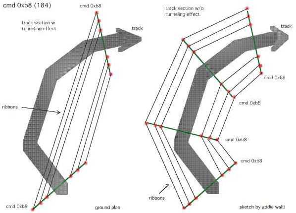
(b8_tun.jpg)
[MK wrote a tutorial about dealing with scenery. It is to be found in
the tutorials page of the track editor homepage]
MK: "With this cmd you can "turn on" individual ribbons and/or banks depending on the value in argument a2. The ribbons are showing up no matter what detail level is set in the game (in opposite to 0xd9)"
a1: Offset Into Sector
a2: Location Code Type
B
Do ONLY insert this cmd at the same position as a 0xaf/0xb8, 0xc0/0xb8 or 0xc1/0xb8 pair. (see original tracks for reference). See 0xb0 for an example of a gfx-bug that can happen when not following this rule.
To switch them off again, use 0xb0
Default: Ribbons/Banks off
a1: ?Offset Into Sector; mostly 0; in f1ct04 there is a value=2
a2:
Location Code Type
B; typical values : 0 1 2 3 4 5 6 8 10 15 (40 f1ct09)
a3: ?Location Code
Type B; typical: 0 1 2 3 4 5 6 8 10 15 16 (20 30 80 f1ct09)
most of the
time a2 is equal a3; exeptions e.g. in f1ct03 f1ct05
MB: take a
look at the 0xba cmd. it does about the same as connect [bridge] fences...
MK: This command is used to force the scenery to "shortcut" the track.
When scenery is made in a curved tracksection, normally the scenery follows the
curvature of the track. When this command is used, the scenery makes a shortcut,
thus following a STRAIGHT line between two scenery-connection points (0xB8
cmds). Note that the scenery5 command is a SWITCH that can be set for some part
of the track, and some ribbons using the location code.
The a2 value
(and/or a3 value) indicates to which ribbon- locations the command is applied,
you can thus force individual ribbons to shortcut.
Normally, you use this
only on the INside of a corner.
See also section 3.5 [in scenery
tutorial]
MK: "OK, OK, maybe it's by default "straight", but then switch it to
"round" by placing one of those commands. It's a switch."
(see f1cts 03 05 06 12) just 1/track (?)
a1: Offset Into Sector; typical values: 0 2 3
a2: Location Code Type
C; (location of texture); typical values:5 9 14
a3: Length; (of the
mapping-area, follows the direction of the ribbon); typical values: 10 14 40
63
a4: Texture ID; typical values: 33 160 198
a5: Repeats; (within length
of the texture; repetition horizontal); typical values: 1 4 5
PLK:
Command 0xbb (187) is a texture mapping command which works exactly the same as
Cmd 0xbc
(188), but does not allow you to alter rotation, resolution or y offset. The
usage is:
a1 - distance into sector;
a2 - texture location;
a3 - length
of texture;
a4 - texture ID;
a5 - number of repeats within length (this
last value should always be balanced as a rounded proportion of the length, ie
length 12 number 4, otherwise the last repeat can be cut off).
It's hard to see why this command exists, as it is only used once in f1ct05,
and I have not seen it anywhere else as yet.
with this cmd we do define an area, where a texture gets mapped. first we
define the size of the area, 2nd we select the texture and define how it gets
mapped on the definend area. we define repetition horizontal and vertical,
rotation.
a1: Offset Into Sector
a2: Location Code Type
C; (location of texture)

a3: Length; (of the mapping-area, follows the direction of the ribbon)
a4:
Texture ID
a5: Repeats; (within length of the texture; repetition
horizontal)
a6: Vertical Resolution; (16 is full texture)
a7: Vertical
Shift; (within the texture)
if this shift is somewhat greater than 0 and less
than the vertical resolution of the texture, then the texture gets shifted
upwards by this amount. that means the upper margin gets cutted and pasted at
the lower margin.
a8: Rotation; (of the texture in steps of
90degrees.
value 0-15 : 0 degrees
value 16-31: 90 degrees
value 32-47 :
180 degrees
value 48-63: 270 degrees
common rotation values (to avoid distortions) : 3 (0 degrees), 19 (90 degrees), 35 (...), 51, 67, etc.).
MK: When applying a texture to a fence/ribbon/bank/verge, it
may be upside down, or wanted upside down or turned. The code to do this is the
arg8 - X angle, with codes 16,32,48 respectively, for 90-180-270 degrees
rotation. (cost me some time to find out, typing 90 the first time, when you
KNOW you are working with computercode, is quite stupid. The Doom-editing I once
did helped me remind that EVERYTHING goes in powers of two.) The interface box
on this command is pretty bad in 156, almost all changes are not working.
Instead, I use the properties box which is difficult because the textures have
no names, the places are just a number and so on. Not too difficult, but maybe
more of a hint to Paul Hoad. Seems like a little bug in the TE. Also, the nrows
is the number of rows of pixels on the bitmap that is mapped. Not the number of
mapped bitmaps that you want on your ribbon.
For example, for a regular
advert, the number of pixels (nrows) is 16. On the other hand, the nbitmaps
command IS the number of times you want your bitmap placed on the ribbon. For
example, a fence with length 20 and only one nbitmap, give a very stretched-out
advert on the fence. I use an average of 1 advert per 4-5 units of length, which
looks OK to me. Beware of the short adverts (like Castrol) because they will be
very streched out.
If you want to use only part of a texture, then you
can make an a7, vertical shift. The unit is pixels. But then, the lower part of
your texture gets invisible or ugly. Then decrease the a6-"nrows" to define the
fraction of the texture that you want to display. (remark of author: AZ
used exactly this trick to have working gravel traps in several different colors
in his new Melbourne-track!)
For example, if you want to use only the
lower part of texture 36: Normally, the mobil advert is included in this
texture. (look at por2.jam) and this advert is on the top, 20 pixels high. The
whole texture is 32+20 = 52 high. Now we want 32/52 part of it to be seen, this
is 0.61. This is (almost) 10/16, so I insert the values nrows=10 and y-offset =
20. Get it?
(This texture is the fence to hold you from falling of the cliff
on tunneltrack, and also the marshall-post tower. It has a finer look than the
112 texture)
JV: "When dealing with additional tarmac textures you may want to
try different values of a6. E.g. in Monaco it is 8 and in Silverstone it is
16."
1/track. always in t0
a1: unk; ?always 0 (ever?)
a2: Direction;
(0..65535? means 0..360 degrees)
a3: Angle of Sun Above Horizon; typical
values: 7000 .. 12500
PLK: a2 is definitely a rotational value.
The sun in Portugal has a value of -3640. In the track I'm working on now,
objects which face me while I exit the pits where in deep shadow. I changed the
value to -18640, and the sunlight had turned around (anti-clockwise) to light up
these objects.
a1: Offset Into Sector; typical values: 0 .. 100
a2: Location Code Type
E; typical values: 4 .. 63 (16 = left bank, 32= right bank, 48 =
both)
a3: View Distance; valid range 60 - 255
For a brief introduction in the subject "View-Distance" please have alook at the old view distance cmds 0x81 (129) and 0x82 (130).
If you insert a cmd 0xbe (190) or 0xbf (191) and set a3 to a value smaller than 60, the view-distance remains about 60. If you set a3 greater then 60, the view-distancegets increased to the specified value. If you set a3=100 the view-distance is 100 track-length units. In opposite to the old view-distance-cmds 0x81 (129) and 0x82 (130) you can define what should show up in the extended view distance. With a2 you can do this.
Road and ribbons show up always. With a2 you can also enable the other locations. So if you e.g. set a2=19 the following locations show up: road, ribbons, verges and left bank.
It looks to me like you only need these two cmds to set the view-distances. But in the original tracks these cmds are always inserted together with a cmd 0x81 or 0x82. IF the are inserted as a pair ALWAYS the view-distance is set by the old cmd 0x81 or 0x82 and the location is set by the new cmd 0xbe or 0xbf. This means a3 of 0xbe gets overridden by a2 of 0x81 and a3 of 0xbf gets overridden by a2 of 0x82.
This is a bit strange. Maybe there is some (yet hidden) double meaning, see FAs statement at the cmds 0x81 and 0x82 ...
If you want to go beyond a range of 255 you may need to work with cmd 0xc5 (197).
These cmds define position and angle of a single swivel-arm for the scenery-ribbons. The x- and z- coordinates of the scenery-ribbons are defined in the cmd 0xb8 (184).
a1: Offset Into Sector
a2: Angle Of Arm; (0xc0: useful: negative value;
0xc1: useful: positive value)
For extensive description of the meaning of swivel arms, see cmd 0xaf
(175).
possibly scenery
a1: ?Offset Into Sector; mostly 0 (exept e.g. f1ct05:
6)
a2: unk; typical values: 0 1 2 3 4 6 8 (10 f1ct11)
a3: unk; typical
values: 0 1 2 3 4 6 8 (10 f1ct11)
a2 is equal a3 most of the time (exept
e.g f1ct05, f1ct11)
always? following b8; or b0 that is following
b8
a1: ?Offset Into Sector; mostly 0 (exept e.g. f1ct07: 1 6)
a2: unk;
typical values: 0 1 2 3 4 5 6
a3: unk; typical values: 0 1 2 3 4 5 6 8 10
(most of the time equal to a2; exept e.g. f1ct11 f1ct16)
MK: 0xc3 bridge scenery command ?!
(see f1cts 12 13 14)
possibly scenery
a1: unk; always? 0
a2: unk;
typical values: 0 1 2 4 8
a3: unk; typical values: 0 1 2 4 8 ?always equal to
a2
a4: unk; typical values: 3 32 48
a1: Offset Into Sector;
a2: begin far-view section; distance from
s/f
a3: end far-view section; distance from s/f
a4: location code type
D [thanks to DC]; defines what parts of scenery is visible
a5:
unk; always 0 in the original tracks
a6: unk; always 0 in the original
tracks
a7: unk; always 0 in the original tracks
(a8: periferal angle
[thanks to BC!]; typical values: 0 1024 3072 5120 14336 -512);
a1: Offset Into Sector;
a2: Length of Far-View-Window; within this
"window" the far-view-section is visible (if the arguments of 0xc5 are set
correctly)
The following is a screenshot of a slightly modified Imola track from the first specific 0xc5 experiment by the author:

The cmds 0xc5 / 0xc6 are used for defining "Far-View". To understand the
necessity of "Far-View" you have to understand the limits of the "View-Distance"
concept. For descriptons of the "View-Distance" concept see cmds 0x81, 0x82, 0xbe,
and/or 0xbf.
There you see the View-Distance is limited to a distance of 255 track-length
units. In long straights or twisted tracks, or tracks with crossings it can be
necessary to have a greater view-distance. Thats when 0xc5 together with 0xc6
come to play.
In the following image we see a clip of the Bern-Grauholz track made by the author. This track features a crossing beyond the "regular" view-distance. The cmds 0xc5 and 0xc6 make it possible to see the cc-car on the bridge. The figures in the track-sectors are distances from s/f !

We need to insert both cmds in the same track-sector. In the example above, the cmds are in the track sector at distance 125 from s/f. 0xc5 at first (or more than 1 of them), 0xc6 afterwards. With 0xc5 we define what part of the track should become visible. We define this part by giving the distance from start s/f. In the above example we insert a2= 538 and a3 = 548 for defining the section visible where the bridge is. Of course we have to take care of the heights when making an arrangement like this !
There are two more arguments from interest in 0xc5. With a4 we can define what parts of the scenery should become visible. With a8 (if available) we somehow can define the periferal angle of visibility of the far-view-section. Its not yet clear how this argument works in detail. A possible approach could be: imagine a line from your head (point of view in the game) to the "far view"-section. This is zero degrees. Now imagine you turn your head. This is periferal angle. 0, 90, 180 and 270, all +- about 20 degrees seem to be visible all the time (e.g. at a8=0). With increasing the value of a8 you can "fill up" the gap. However you may want to check out several values for getting the best result.
Once the far-view-section is defined, we have to "open a window" by a cmd 0xc6.
More: 0xc5/0xc6 is not only useful for defining and enabling far-view-sections. It is also very useful for defining and enabling "rear-views" ! Imagine a hairpin. When you approach the hairpin you have the whole section in front of you. Then you turn in. When leaving the hairpin you see the road ahead of you. But you also should be able to see the road that approaches the hairpin (where you drove a few seconds ago). But in gp2 its not possible to look forward and behind at the same time, and the mentioned section IS behind, although you see it in front view ! Thats where you can use 0xc5/0xc6 also. With 0xc5 you define the part of the track you do not see now, and with 0xc6 you define a window in front of you.
Switching number of arguments
In some original tracks this cmd has 7 args, in other original tracks it has 8 args. The switch for the number of arguments is to be found in the track config section, track-sections, in the same place where you find the pit-side-switch. The TE ALWAYS inserts 0xc5 (197) with 8 args when rightclicking a tracksector in the track tree and choose "insert track command"), whatever the switch is set to. So if the switch is set to 7 args and you insert a cmd 0xc5 anyway, your track is lost ! (save and load it to see what i mean).
If you want to set up some far view areas, you may want to work with the cmds with 8 args, because a8 is a very useful argument. If your track features only cmds 0xc5 with 7 args, you can change this be deleting ALL cmds 0xc5 (197), then setting the mentioned switch to 8 args and then inserting new cmds 0xc5 (197). This works well, i tested that. But you may want to make a backup of your track anyway before trying it !
Changing the switch means inserting a different number. The following values are ok (in terms of inserting a cmd 0xc5(197) with the TE): 3968, 3978, 8064, 8074, 40832, 40842. The following table shows the values that are not ok and the values that should replace them BEFORE inserting some cmd 0xc5 (197):
| value not ok! | replace by |
| 3456 | 3968 |
| 3466 | 3978 |
| 7552 | 8064 |
| 7562 | 8074 |
| 40320 | 40832 |
As the watchful reader already noticed, basically its adding 512, which means simply setting the 0xc5-flag.
More comments:
MK: (on a problem with a "flying armco")
"I found a solution. I told you it was leaking through with the far-view
window I set up there. So I decreased the length of the window, and it
disappeared. But there are some more things to say about.
First, I had a
far-view that went on until exactly the finishline. It is not possible (as far
as I have seen) to get the entire area around s/f in one window, so you either
have the last part, or the first part of the track. And only one window is
active at any time.
Second, I have seen the "flying armco" before, coming
from objects.The "Flying Armco" goes from the point where the problem is, to the
"disapperaring point" in the middle of the screen, on the level of the horizon.
Like it was infinitly long. On these objects, the reason for the "F.A", was that
I made one or more "polygons" length zero. For instance, by putting two vertices
on top of one another (in 3D) which gives the connecting line a length zero. Or
by setting one of the scale-units length zero.
Anyway, GP2 doesn't like that
sometimes, and perhaps by some division operation, instead of zero, the length
of that section becomes infinite.
Point is, I couldn't find an object
with any length zero there. But perhaps the fact that I made the far-view window
get up right untill s/f, made a similar division-problem, and thus the error. By
cutting the window short by 4 units, the problem disappeared anyway."
"... the 0xc5, and this command seems sometimes to only work at a specific
angle
in which you see the "window-stuff".
PKA on a8 of 0xc5: value 8= radius of vision 16384= 90
degrees
"yeah the angle is set from the place the command is triggered,
so if you're
on a straight then 0 will do the job but once you turn things
will
disappear."
*0x81 / 0x82 be/bf don't have any influence if there's a c5 code in the vicinity."
DC: "Strange flashing switch in view could have something to
do with using 0xc5 values that span the start/finish, i.e. the end and beginning
of the track.
I found that if I used values that stopped just before the
end of the last inch of track, the walls no longer flashed. Also, when I used
values that started at the beginning of the track and ended where I normally
ended the view, this second scenery bug was fixed.
Now the problem is
that it is hard to string together 2 or more of these commands without making
the view look poor, like one section switches on when another switches off when
you pass a point. Also, when I make a third command that spans the small area on
either side of the S/F straight, this small area flashes."
"Oh yeah I forgot, if its not already known, Cars and Objects are always seen
with his command, even when A4 = 0. "
LD: "0xc6 seems to work
much like the 0xdb (219)
"Show Pits Through Ribbons" and/or 0xd3 "View
Into Pit Entry". I had to put the 0xc6 into t107 of Van Indy, screwed up the
fences a little, but it was a compromise between Not beeing able to see into the
pits, or some weirdness with the fences."
BC: "I also discovered that if the sections specified in the Oxc5
and Oxc6 commands overlap, when you are in the overlap section, nothing shows
up, not even objects! What I am referring to is in the Oxc6 commandd, the values
define the distance that the Oxc5 is inacted. The Oxc5 defines the distance from
the S/F line. So, if those two sections overlap, that is where everything shuts
off. For people using tracks with oxc5 and Oxc6 commands such as Imola and Spa,
if you leave these commands in, it could cause these sort of problems if you are
substantially revising the track. I also experimented with multiple Oxc5/Oxc6
combinations. What happens is the last command is the one recognised."
DC: "For multiple arguments, you mean:
0xC5, 0xC5, 0xC5,
0xC6 in order. I found that the last one works too, but only for objects, I
think. So, an object would not show up unless it was in the last C5. In Monza,
trying to fix the view of the S/F straight, I have to split it into 2 commands,
since there is a problem of using 1 command to go past the start and end of the
track. Since the pit building is defined in the last sector of track and
corresponds to the first C5, the building does not show up.
For the
overlap, you mean when C6 value lies within the values for a2: and a3: of 0xC5?
"
BC: "Yes. Since the A2 of the Oxc6 command determines the distance
from the point of the command that the Oxc5 section defined is visible; if the
area defined by the Oxc5 is within that distance, then that is the point where
everything shuts off. Since the Oxc5 defines the section as distance from the
S/F line, it is not so obvious until you actually drive."
It was MB who originally turned my attention to the 0xc5 cmd in
the original Imola track.
a1: possibly Offset Into Sector (see f1ct04)
a2: ?location code type D; 16
32 48 272 512 544 560 1297 1570 16384 16416 24576 25088 (see f1ct02)
a3:
?location code type D; typical values: -1 (06 13) 0 (03 04) 2048 4096 6144
To find in t0 of most of the original tracks. Looks and works similar to 0xbc
(188)
a1: unk
a2: Location Code Type
C
a3: Length Of Repeated Section
a4: Texture ID
a5: Repeats;
(within Length of the texture; repetition horizontal); usually 1
a6: Vertical
Resolution
a7: ?Vertical Shift; (within the texture)
a8: Rotation; (of the
texture; in steps of 90degrees; common values: 3 (0 degrees), 19 (90 degrees),
35 (...), 51, 67, etc.).
Now the full description of
NP:
This is the scenery definition command that defines what the
default textures will be on the left and right floors and sometimes left and
right fences, as you already know. There are still a number of unkowns which
I've managed to work out.
I found that this command is closer to the 0xbc
command than was thought. As in that command, Arg(3) is the length, but here it
means the length that the texture is drawn on, and then this length is repeated
x times over the total length of the track, x being track length/length value.
Arg(5) is the number of times the texture is repeated over the length value in
Arg(3).
Arg(6) is the number of rows displayed. Arg(8) is the x angle as
well. Arg(1) I'm not too sure about, as I couldn't really see any difference
from the small change I made to it, so I'll get back to you on this one. You
would assume that Arg(7) is the y offset as in 0xbc, but I didn't test
this.
With this cmd you can set colors of the gp2 palette. You find a full
description of that cmd in the tutorial "Colour Control in GP2" of DS and
addie walti. The picture shows an example of what can be done with this cmd
:)
(c9_ex.jpg; click to enlarge) 
(this screenshot you find
also in the mentioned tutorial)
The arguments of the cmd 0xc9
are:
a1: ?always 0
a2: Palette index 1
a3: Palette index 2
a4:
Hue angle 1
a5: Hue angle 2
a6: Saturation 1
a7: Saturation 2
a8:
Brightness 1
a9: Brightness 2
Arguments by DS:
a1: ?unused
a2: Distance to Height1
a3:
Distance to Height2
a4: Height1
a5: Height2
NP: These two
commands define the charcteristics of the two kerb types; A and B. These two
commands appear only once each in in every track. Once again, for all tracks
except F1ct16.dat, these are found in track section zero. For F1ct16, they are
found in track section 6. It actually doesn't matter where within the track
these are, but there's no need to move them anyway, so don't bother. If you
place a second 0xca or 0xcb kerb command somewhere into the track, this will
basically overwrite the existing command, such that kerb characteristics of this
kerb type for the entire track will come from the new command, not the existing
one. My advice; don't add, or move 0xca and 0xcb commands. You'll just confuse
things.
Each of these commands has exactly the same arguments
(variables), so we'll look at them together. The five arguments are:
a1 :
Unused (always set at zero)
a2 : Profile - the cross-section of the kerb.
Affects, and is affected by, height and width values.
a3 : Kerb
Width.
a4 : Height at Track - How high the kerb will be at the track
edge.
a5 : Height on Verge - How high the kerb will be at the edge fartherest
from the track.
We'll leave the Profile till last, as it is the
hardest to explain, and your width and two height values will change how this
works, so we'll start with them.
a3 : Kerb width
This is simply
how wide the kerb will be. possible values are from zero to 500+. I say 500+
because I've never gone any wider than this and for existing (real) Formula One
circuits, this is about as wide as kerbs get. Interlagos, in Brazil, for
example, has very wide kerbs, which would be about 500. Just remember, that when
you set a very wide kerb, unless you adjust the CC-line (hard), or mess around
with the track widths(relatively easily, explained elsewhere in the tutorial),
you, the human driver, will be able to make full use of them, but the CCs won't,
which will be in your favour, obviously.
a4 : Height at track.
This value sets how high the kerb will be where the kerb meets the track.
The idea of the profile value (a2) is to move this height between the track edge
and the far edge, but more of that later. The possible range of values for this
range from zero to 32+. 32 is the highest value that you'll find in the original
Microprose tracks. Trust me, I don't think that you'll seriously want to make
this any larger; 32 makes a big enough kerb as it is.
a5 : Height
on Verge
This value sets how high the kerb will be at the edge fartherest
from the track. It is in the same units as a4. Possible range of values are the
same as for a4. Contrary to what you might think, this value does not
necessarily have to be the same as or greater than a4. With clever usage of a2,
the profile, you can do this and not get a strange looking
kerb.
a2 : Profile
This value remained unknown up to and
including TrackEd 1.56. I discovered it a few months back, but it was only now
(as I was typing the Height at Track explanation, in fact!) that I have an exact
explanation for it. The function of this value, is to define how far from the
track edge the Height at Track (a4) will be. It sounds funny, but trust me. The
best way to look at this is in a two dimensional, x-y axis system. In this
system, Kerb Width (a3), and Profile, are x values. Both kerb heights,
therefore, are y values. The origin of this graph ((0,0) - where the x and y
axis meet), is the point where the edge of the track meets the kerb. We will
consider a kerb on the right hand side of the track. For a left hand kerb you
would just mirror the graph.
Let's say that the kerb width is 300, the
Height at Track is 20, and the Height on Verge is 30. Now when the Profile value
is set to zero, the graph, which represents the cross-section of the kerb, will
look like this.
As you can see, from the origin, the kerb will rise
vertically to a height of twenty. From here, the top of the kerb will go to the
point (300,30), which is the end of our kerb. The line drawn from point (0,20)
to point (300,30) is not a straight line. GP2 will always give this line a
small, positive curve. This means that this line has a hump, or rise in it. This
is just to smooth things out so to speak, and it is not possible to alter this.
Going back to the graph, you'll see that the kerb created is undesirable. No
kerb I have seen has such a large vertical edge to it at the track edge.
Now let's do the same thing again, but using a Profile value of
20.
You'll notice here that the profile value has moved the Height at
Track value 20 units to the right. The kerb now begins at the origin, then rises
to the point (20,20). Once again, this line is not perfectly straight. As
before, the top of the kerb will then go from this point to the verge edge,
namely point (300, 30). As you can see, we now have what you would consider a
proper kerb.
You can probably work out for yourself that by making the
Height on Verge larger than the Height at Track, and using a good profile value,
you can make a kerb which rises from the track edge, and then falls away from
the point (profile, height at track) to the verge edge) and still have a
'normal' kerb, as I mentioned previously.
The Profile value is in the
same units as Kerb width (Arg 3), and you can actually make this larger than the
width value. However, if you do this, you'll notice that kerb is rather stupid
looking, so doing this is not practical.
[see also cmds 0x8e and
0x8f]
not used in original tracks; uncovered by VIH:
a1: ?unused
a2: rotating scenery (similar to track start angle); valid
values 0..65535
a3: horizon height; valid values 0 .. 32767 (higher values
give 0 height)
So a3 "zooms" horizon. I found that the default value (no
0xcc commands on track) is between 600-650. It's hard to know exact value. Maybe
640.
Low values make horizon smaller and high bigger. If used 0, there
is no horizon. And 1280 (or near) dublicates the size of horizon.
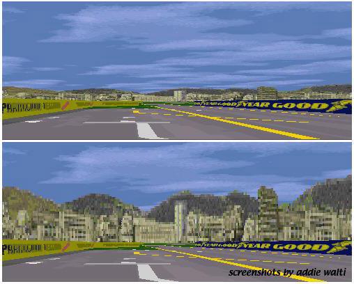
(upper with a2 = 0, a3 =640; lower a2 =0, a3
=2400)

(a2 =2048, a3 = 2400)
It works global only!
These cmds are not available in TE of PH version prior to 1.8.7 and TE of VIH
prior to 0.040.
BEWARE once one of these cmds is in a track, this
track does not load anymore in elder TE versions ! ("Unknown Code 204" and
messed up track in TE of PH and lockup in TE of VIH!)
Lights up or darkens the textures.
a1: Offset Into Sector
a2:
Location Code Type
A
a3: Length; (of the darkend or light up zone)
a4: Light Up Or Darken
Factor; MK: seems to be between 0 (dark) and 15 (bright).
Example
in Monace t22-t24

Upper: original monaco-track with 0xcd (205) in t22
Lower: original monaco-track w/o 0xcd (205) in t22; the windows of the massenet hotel are darker
In this example the cmd 0xcd (205) is used to lighten up the frontwindows of the massenet-hotel. Or in technically terms: to lighten up the texture on ribbon 4.
probably scenery
f1ct04 only?
only once only in f1ct04 t68 (tunnel)
a1: unk; typical
values: 0
a2: unk; typical values: 4
DS: It occurs only once in f1ct04.dat, Monaco. It appears in t68, the sector just before the tunnel. Its argument is (4). Removing it caused the tunnel roof section bleed through the right building wall as seen from portier corner.
LD: "Its just another scenery cmd. seems to be assigned to a ribbon.
a2= 4 means assignement to ribbon 4"
f1cts 01 03 09 14
a1: ?Offset Into Sector; typical values 0, 4
a2:
?distance of effect; typical values: 39 50 100 160
DS: It always appears in track sectors before the start of the pits. Usually at some distance. However the second argument always covers the whole of the track upto or just beyond where the pit fences begin. My conclusion is therefore to allow the pit building and pit objects to be seen at a distance through the pit fences but not through the track fences.
There are two arguments to this cmd. The first i believe is the offset from the position of the track where its located. The second marks the distance at which the cmd has an effect, and i believe in theory could run for as long as the track.
Its use appears to be to allow objects to be seen through or across fences.
Aside from this observations it would appear as a bug if used in the wrong
place.
(see f1ct04 t51 f1ct10 t19; f1ct13 t30)
a1: ?Offset Into Sector;
typical values: 0 .. 50
a2: ?Location Code Type
D; typical values: 4 16 32 48 512 544 1024 1056 6160 6144 7200 8192 16416
24576 24608 24624
a3: ?Location Code Type D; typical values: 0 2048 4096 6144
possibly a2 and a3 are ribbon locations
The loc code looks to me like
type D rather than type A !
some here and there we see a 0xd0 with both a2 and a3 =65535
(-1)
PH: "I also notices that the 0xd0 commands seem to prevent
scenery panels flashing, but I didn't do anymore experimentation here."
(see f1cts 02 10 15 16) 1/track in one of the last track-sector ?
a1: unk;
typical values: 0 5
(see f1cts 02 10 15 16) 1/track in one of the last track-sector ?
always
along with 0xd1
a1: unk; typical values: 2 6 10
a2: unk; typical
values: 132 140 145 155
see also 0xdd
!
a1: Offset Into Sector
a2: View Distance; (into pit lane entry); typical
values: 10 .. 42
By the help of this cmd, the pit lane entrance becomes visible if you have
not yet entered the pit lane.
As soon as you have entered the pit lane it
becomes visible anyway, but as long as you are outside, visibility (view
distance) depends on a2 of this cmd.
The pitcrews do not get visible.
For further descriptions see pit lane tutorial
f1ct12 only? only once
a1: Offset Into Sector; 0
This cmd works similar to cmd 0xd3, but with unlimited view distance. As soon as you pass this cmd, all pit lane is visible from the track. f1ct12 (monza) is the only original track where you see from the entry "through" the pitlane to the exit. Thats why this cmd is used but there.
If you use this cmd at the entrance, you also have to use cmd 0xd6 (214) at the exit, et vice versa.
You may experience gfx-trouble (e.g. pit lane armco bleeding in regular
track) if you use these cmds in pit lanes that are not
all-straight.
a1: Offset Into Sector
a2: View Distance; (into pit lane exit); typical
values: 14 .. 30
By the help of this cmd, the pit lane exit becomes
visible if you look into the pit lane from the wrong end and have not yet
entered it. As soon as you have entered the pit lane it becomes visible anyway,
but as long as you are outside, visibility (view distance) depends on a2 of this
cmd.
The pitcrews do not become visible.
For further descriptions see pit lane tutorial.
f1ct12 only? only once
a1: Offset Into Sector; typical
values:15
This cmd works similar to cmd 0xd5, but with unlimited view
distance. As soon as you pass this cmd, all pit lane is visible. f1ct12 (Monza)
is the only original track where you see from the exit "through" the pitlane to
the entry. Thats why this cmd is used but there.
If you use this cmd at the entrance, you also have to use cmd 0xd6 (214) at the exit, et vice versa.
You may experience gfx-trouble (e.g. pit lane armco bleeding in regular track) if you use these cmds in pit lanes that are not all-straight.
PH: it simply stores the position of the sector in which it appears
which might mean that it may be trigger for something.
(see f1ct11, f1ct13, f1ct14; only 1/track)
a1: unk; typical values: 2
25
It sets up the visibility of the pit lane entrance
OO: cmd 0xd7 seems to control some factor at the pit exit, as it
prevents you from seeing into the pits at its exit.
PH: it simply
stores the position of the sector in which it appears which might mean that it
may be trigger for something.
Maybe this spa screenshots give some hint:

To me it looks like it sets up the drawing order in a specific way. See also 0xdb
(see f1ct01 f1ct13, f1ct14) only 1/track
a1: distance of effect
This cmd enables the view into the pit lane from the track accoring to the setting of the 0xd3 cmd on a distance given by a1. If 0xd8 (216) is missing you see into the pit lane through the pit entrance. As soon as the entrance is passed, the pit scenery disapprears. But if you insert a 0xd8 it does NOT disappear !
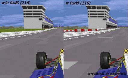
Typically you insert a 0xd8 in the track at about the pit entrance, where the "two worlds" are connected. As a1 you enter the distance of the effect. Beware the distance has to be smaller than the remaining section of the track until the s/f line. If the remaining section is 40, like in original interlagos f1ct01.dat, the maximum a1 is 39, else the pit lane scenery wont show up at all.
The length of pit lane showing up is given by a2 of 0xd3. In the following examples i took original Interlagos f1ct01.dat, set a1 of 0xd8 in t96 to 39 (max possible value). This gave me the the left screenshot in the following image:
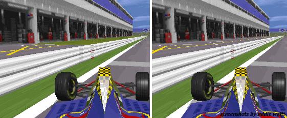
(In original interlagos a2 of 0xd3 in t88 is set to 42). After that i set a2 of 0xd3 in t88 to 72 and got the right screenshot in the image above.
The pit lane scenery was only visible in front view. When driving in the wrong direction the pitlane scenery wasnt visible anymore.
Seems not to work in far-sight (see 0xc5)
It was PA who turned my attention to this cmd !
MK: With this cmd you can "turn on" individual ribbons and banks depending on the value in argument a2. The banks are showing up no matter what detail level is set in the game. The ribbons only show up in medium and high detail level. ...and they remain textured whatever is set in the graphics-setup of the game.
If you want them showing up no matter what detail level is set, you have to use 0xb9 instead)
a1: Offset Into Sector
a2: Location Code Type
B
Do ONLY insert this cmd at the same position as a 0xaf/0xb8, 0xc0/0xb8 or 0xc1/0xb8 pair. (see original tracks for reference). See 0xb0 for an example of a gfx-bug that can happen when not following this rule.
To switch them off again, use 0xb0
Default: Ribbons/Banks off
a1: Offset Into Sector; typical values: 0 1 3 4 9 20 54 99 (see f1cts 11
12)
a2: Location Code Type
B; typical values: 1 2 4 6 8 10
MK: The first argument is
(as always) the offset into the sector. Set it to 150 to see it is.
The
second argument is a location code, type
B from the table in the scenery tutorial [or in the glossary of this
document].
The command SEEMS to switch off the selected ribbon, AND
delete any applied textures to it for ~100 tracklength units BEFORE the command.
I saw that when setting the offset to 150. Then, the first part of the track
actually HAS texture applied to ribbon2, but then it disappears, and at the
given offset, the ribbon itself disappears completely. Well, maybe not
completely. The point were the ribbon disappears, shows a flash that indicates
that maybe the ribbon is put to the other side, or zeroed.
Of course, I
don't know anything about why this command exists and works like this, it seems
"shorthand" for two or three commands that should be inserted otherwise.
Best bet is to remove the command I guess. I have a tendency to hate things
I don't understand so I use that approach with most "unknown" commands.
MK: I wish to emphasize that it was GN who came with the
initial problem, and draw my attention (and surprise) with a first
description.
Thanks Graeme!
f1ct11 only? t0 only?
a1: unk; typical values: 34
Cmd 0xdb (219) defines the sequence of drawing track- and pit lane scenery
gfx. This cmd can be found (only) in the original Spa-track f1ct11.dat in t0. In
spa you have a hairpin immediately following the s/f straight and after that
another straight (towards eau rouge). Enclosed in these two straights there is
the pit lane, the pit building in particular. It seems like the gp2.exe normally
draws first the pitlane scenery, then the regular track scenery (covering
appropriate part of pitlane scenery and objects). So in our case the trees of
the right side of the straight after the hairpin would become pasted over the
pit building. but here comes 0xdb.
Cmd 0xdb (219) seems to tell the
gp2.exe to switch the sequence of drawing there. its parameter seems to be (once
more) an offset into the sector. So with a cmd 0xdb (219), the gp2.exe first
draws the regular track scenery beyond 0xdb, then the pit lane scenery, then at
last the track where you are standing, if you are standing before the cmd 0xdb
(219).
You can check this easily by removing the cmd 0xdb (219) in the
original Spa-track and then have a look at the pit building, standing in the
middle between s/f line and hairpin.
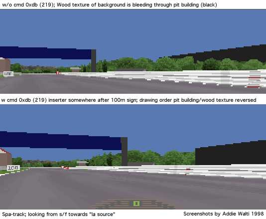
another effect can be seen, when looking from the
track into the pit exit ...
but here it needs some more experiments (any volunteer?)
summary:
you just need the 0xdb when you have a layout of
track and pit lane similar to spa. In all other cases do remove it (and save a
lot of gfx-troubles) !
PH: it simply stores the position of the sector in which it appears which might mean that it may be trigger for something.
see also 0xd7
f1ct11 only? t103, one of the last sectors
a1: unk; typical values:
0
a2: unk; typical values: 70
Not used in the original tracks.
This cmd seems to discover amazing talents of inconspicuous cmds like 0xd2 (or 0xdc ?). If you insert a cmd 0xdd in t0 and AFTERWARDS a 0xd2 also into t0, you can control the overall grip on the track. Full credit goes to OO Obi Offiah ! The first working example was sent to me by MB.
The argument of 0xdd and the first argument of 0xd2 seem to be of no importance (you can let them at 0).
With the second argument of 0xd2 you can set up the grip level. MK: a2 is grip level. "normal" is 16384, if you want mega-grip, use 32767 (loews hairpin in 5th), if you want to try GPL, use around 11000. An icy condition is around 4000, almost zero drivability.
PH: ("Grip levels")
3 - Torvill and Dean Special
1000 - Ice
Field
8000 - Wet Race Conditions
16384 - Normal Dry Race
20000 -
Super Stick Tyres
40000 - I wanna go for land speed record!
MK: "I refer to the 0xD2 as a "gravity constant" change command. I
thought (as we all do) that it meant track-grip, but it does
not. I tested
this on StwuLake, there's a nasty jump there where you can get 4 wheels off the
floor if you want. But when I added the 0xd2 with
a high value [e.g. 26000], the tyres stayed glued to the track! And that happens
also when the car is pushed onto the track more, (while if it was the
friction-coefficient that changed, you would still go in the air). But, I'm not
sure whether it influeces the gravitational pull of the car (IE make the car
heavier), or whether it influences all normal forces (therby also multiplying
the downforce of the wings). I have stong suspicion it is the latter, it
influences both the "mechanical grip" and the "aerodynamical grip"
MB: 0xdd is an evil cmd :) gp2 crashes when placing it in a pit sector and in a track sector it makes the car jumping in the pits.
a1: unk; ?always 0
a2: start of black flag area, offset to s/f; for valid
range see cumlative length in track data table
a3: end of black flag area,
offset to s/f; for valid range see cumlative length in track data table
a4:
speed limit in black flag area; typical values: 45 .. 150 (kph or mph? probably
mph)
PH: Black flags are defined in track sector 0. they consist
of flags on the left or flags (0xDE) on the right (0xDF). So choose the section
you want to add the flag to.
(see f1cts 03 09 10 11 12 14 15 16)
a1: unused; ?always 0
a2: Adjust
Height2; typical values: 24 28 36
see also the other kerb-cmds
Not used in original tracks; uncovered by VIH:
It has been said that there are no commands. But I tested:
Commands 0xE1,
0xE2, 0xE3, 0xE4 and 0xE5 are valid. With 1 argument. But at least they have no
visible effect. But cmds above 0xE5 are not valid. I tried those with args# up
to 4, but GP2 crashed every time. So I think that 0xE5 is the very last command
that is described in gp2.exe. 0xE1 - 0xE5 are described, but it is totally
different matter, does it have meaning.
These cmds are not available in TE of PH version prior to 1.8.7 and TE of VIH
prior to 0.040.
BEWARE once one of these cmds is in a track, this
track does not load anymore in elder TE versions ! ("Unknown Code 204" and
messed up track in TE of PH and lockup in TE of VIH!)
0xff (255) is said to mark the end of track data.
Chapter by NP
Adding commands to track sections can be done a
number of ways. The first is to left-click on the track section in the directory
tree, and then right-click on it. This will bring up a menu and you can choose
to insert a track command from here. The other way is left-click on the track
section on the track map, and then go up to the TRACK menu and select INSERT
TRACK CMD.
To remove a track command, in the directory tree, left-click
the plus (+) sign next to a track section, and left-click on the command that
you want to remove. Then right-click on the command and select REMOVE TRACK
COMMAND from the menu that appears.
To edit a command, left-click on the
plus sign beside a track section in the directory tree, and then left-click on
the command you want to edit to highlight it. In the box at the bottom of the
editor, the various arguments will appear and you can change then by double
clicking on the value you wish to change. Otherwise, double click on the track
command in the directory tree and this will bring up an editing box which is
possibly a more user-friendly method.
Alternative procedures by author
I prefer to copy/paste cmds most of the time. I look around in the neighbored
track sectors for the desired cmd. If i see it, i select and then copy it
(CTRL-C). I go back to my actual track sector, select its headerline and paste
the cmd (CTRL-V). Afterwards i just adjust the arguments of the cmd to my needs.
And for deleting a cmd i most of the time use the cut (CTRL-X)
command.
This is an attempt to unify the terminology between track-editing and the GP2
in order to simplify things. It is also an attempt to introduce some
abbreviations, in order to shorten descriptions and speed things
up.
TE
track-editor
cmd
command
Offset
Into Sector
A lot of cmds do have a parameter saying how far from the
beginning of the sector the cmd "happens". Sometimes this parameter is also
refered as "Start" or "Length Into Sector".
unk
unknown meaning
(of a cmd or an argument)
a7
argument 7 of a cmd; 7th argument
of a cmd
t99
track-sector 99
p99
pit
lane-sector 99
f1ct13 or Slot 13
original track 13 (Estoril);
Slot 13
(all the numbers are just examples)
Sector
A
sector is the smallest piece of a track. A sector has constant curvature and
gradient change. Its length is measured in a unit of 16 feet (4.87m). In order
to keep things simple and short, I use the abbreviation t for track-sector and p
for pit lane sector. So t17 means track-sector 17 and p13 means pit lane sector
13.
Section
General term. Means some track-sectors in a row,
sometimes with a common property. E.g. uphill track-section means some
track-sectors where there is an uphill gradient.
Verge
In order
to unify the terminology in track-editing with the terminology that is used in
GP2 we introduce the term Verge. It labels what was formerly known as bank. That
means, with verge we mean the space between the track and the
fences.
Fence
This is also an "official" GP2 term. It labels
what formerly was know as wall.
Bank
This labels the space
between the fences and the first ribbons.
The last few terms will now be
visualized in a screenshot of the Jerez-track.
(gloss.jpg; click to
enlarge) 
To especially
visualize the new meaning of the term "bank" i switched off all textures but the
these on the banks. In this screenshot on the right side of the track we dont
see the ribbons.
this units are guesses
tracklength. 1 unit equals 16 feet equals 16 x 0.3048m = 4.8768m
height (cumulative height in TE) 40-60 units equal 1m
trackfile-size limit: 62000 bytes (exactly! thanks
grammy!)
| Code | Location |
| 1 | fence left |
| 2 | fence right |
| 16 | verge left |
| 32 | verge right |
| 64 | bank left |
| 128 | bank right |
| 256 | ribbon 1 |
| 512 | ribbon 2 |
| 1024 | ribbon 3 |
| 2048 | ribbon 4 |
| Code | Location |
| 1 | ribbon 1 |
| 2 | ribbon 2 |
| 4 | ribbon 3 |
| 8 | ribbon 4 |
| 16 | bank left |
| 32 | bank right |
Location Code Type C
regular
codes
| Code | Location |
| 4 | fence right |
| 5 | fence left |
| 8 | verge right |
| 9 | verge left |
| 10 | road |
| 11 | ribbon 1 |
| 12 | ribbon 2 |
| 13 | ribbon 3 |
| 14 | ribbon 4 |
| 18 | bank left |
| 19 | bank right |
additional codes (as found by LD and Filou), not usable for
cmd 0xbc
(188) as far as I know
| Code | Location |
| 2 | Type A Right Kerb Outside Part |
| 3 | Type A Left Kerb Outside Part |
| 16 | Type A Right Kerb Inside Part |
| 17 | Type A Left Kerb Inside Part |
| 20 | Road Floor at the Entry and Exit of Pitlane |
| 25 | Type B Right Kerb Outside Part |
| 26 | Type B Left Kerb Outside Part |
| 27 | Type B Right Kerb Inside Part |
| 28 | Type B Left Kerb Inside Part |
Location Code Type D
as found by
DC
| Code | Location |
| 1 | grey road(no texture) |
| 2 | ? |
| 4 | fences/walls |
| 8 | ? |
| 16 | road |
| 32 | verges |
| 64 | banks |
| 128 | all ribbons |
| 256 | pitroad |
| 512 | pitroad lines |
| 1024 | ribbon 1 |
| 2048 | ribbon 2 |
| 4096 | ribbon 3 |
| 8192 | ribbon 4 |
| 16384 | ? |
| 32768 | ? |
| Code | Description |
| 0 | Default (All ribbons) |
| 1 | Right verge |
| 2 | Left verge |
| 4 | Right fence |
| 8 | Left fence |
| 16 | Right bank |
| 32 | Left bank |
For the angles see the following "compass"-sketch by MR:
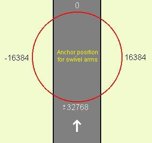
table with degrees and correspondant values (182.044 / degree):
| degrees (clockwise) | value (approx) | negative value |
| 0 | 0 | |
| 45 | 8192 | |
| 60 | 10923 | |
| 70 | 12740 | |
| 80 | 14560 | |
| 90 | 16384 | |
| 100 | 18200 | |
| 110 | 20020 | |
| 120 | 21840 | |
| 135 | 24576 | |
| 180 | 32768 | |
| 250 | 46410 | -19125 |
| 270 | 49152 | -16384 |
| 275 | 50176 | -15359 |
| 285 | 52224 | -13311 |
| 315 | 57344 | -8192 |
it doesnt matter whether you insert the positive or the negative representant of the value.
typical values (as can be found in f1ct14.dat):
11264, 12288, 13312, 13824, 14336, 15360, 16384, 17408, 18432, 19331, 19456,
21504, 24576
44030, 46080, 47104, 48128, 49152, 49213, 49315, 50176, 50183,
51200, 52224, 54272
If you would like to research for the unknown, maybe some hints could help
starting you off. Basically think of it as a whole thing. The cmds and their
arguments are just little pieces of it. So there is NO real weird stuff,
everything fits in someway. Sometimes the solution is much closer than we are
looking for. Sometimes we are looking for a solution too complicated. Remember,
its a game-program for pc, so Geoff Crammond has had to simplificate things in
order to speed it up.
a1 most of the times is the offset, that means the
length into the sector, where a cmd has to happen. Numbers 1..100 could be also
a length (x16ft), or a transition length. Sometimes its not x16ft, but maybe
inch ...
Figures 16384, 49152 or similar could represent an angle, see compass-chapter
for details.
Sometimes a value is said to be always 0 and if you have a
look at the original tracks it is indeed always 0. the question is: HAS it to be
always 0, or is it maybe a hidden gadget ? (we never know
:)
UNSIGNED vs. INTEGER
Big positive numbers, e.g. 65438,
also could be a low negative number: in computer programming everything is
stored in bits and bytes. A typical storing-unit is two-bytes (16bit), also
called word. In such a word you can either store a number 0..65535, that means
2^16 (2 power 16), such a number is called UNSIGNED or CARDINAL. Or it can be
stored as a so called INTEGER number, -32768 .. +32767. But its the same
two-bytes, its just a matter of interpretation. That means a certain number, say
65000, could be interpreted as UNSIGNED 65000, or as INTEGER -535; same
two-bytes, different interpretation. So if an argument of a cmd has typical
values 0..1000 and 64535 .. 65535, this actually smells like INTEGER: 0..1000,
-1 .. -1000. Here the calculation: 0..32767 its the same INTEGER and UNSIGNED;
65535 downto 32768 you have to interpret as -1 downto -32767, calculation:
integer:= unsigned-65536.
UNSIGNED vs. BIT
The same two-word
could also be interpreted as a bunch of bits. So if there are typical values 1,
2, 4, 8 or 16, etc. This could have to be interpreted bitwise. The first bit
from the right is 1, the second 2 the third 4, the fourth 8, the fifth 2^5 (2
power 5), etc. e.g. have a look at a2 of cmd 0xcd, this looks like a typical
two-word that has to be interpreted bitwise.
general
Some
arguments have to be interpreted as direction, where you have to do some
value-to-angle transformation, see e.g. a8 of cmd 0xbc. You may want to look for
cmds that have similar arguments with similar typical values. etc. its chasing
...
Last but not least
If you find something, please do notify
me. I will collect and integrate it in this library ...
The following people are quoted in this document (alphabetical order; with last known e-mail address):
Version 2.7 (Jan 10, 2000)
-reworked 0x8a, 0x8b
-extended
0xcc
-reworked
0xb8
-slight
extension at 0x94/0x95, 0xba
-extended
0xcc
-uncovered
by VIH: 0x8c,
0x8d,
0x93,
0x9c,
0x9d,
0xa5,
0xae,
0xb1,
0xb2,
0xb3,
0xb6,
0xb7 0xcc, 0xe1,
0xe2,
0xe3,
0xe4,
0xe5
-new
0xd8
-extended
by MK: 0xba
-extended
by MK, RP, BP and author:0x85, 0cb4, 0xb5
-reworked
and extended! 0xb0, 0xb9, 0xd9
-drawing-sequence
0xdb
<> 0xd7
?
-view-distance cmds 0x81
(129), 0x82
(130), 0xbe (190)
0xbf
(191) completely reworked !
-reworked 0xcd
(205)
-new location codes D
(thanks to DC) and E
-slight
extension of 0x90 and
0x91 by
PK
-cmd 0x9e(158)
slight extensions
-cmd 0xc5(197)
rework
-cmd 0xdb (219)
description included, finally :) i discovered its meaning (partly) in july 98,
but the info never found its way into the cmd-lib. shame on me !
-slight
extension of type C location code table.
-additional Kerbs description by
RP
-guess on 0xc3 by
MK
-Name change of 0xc8 to
Default Texture Mapping
Version 2.6 (Feb 5, 1999)
-compass
and angle-table in glossary
-location code type C extended
-more specific
describtion of 0x80(128)
-0xc5(197) and 0xc6(198)
-new entries 0xd4(212)
and 0xd6(214). 0xd3(211) and 0xd5(213) brief description
inserted.
-additional remark to 0x8a(138) and 0x8b(139) by
JK
-additional procedures for dealing with cmds in the chapter "adding
commands"
-new approach for cmd 0xaf(175), 0xc0(192),
0xc1(193)
Version 2.5 (Oct 22, 1998)
-extended table of contents
-changed
comments on of MK on cmds 0xb9, 0xba, 0xc0, 0xc1
-removed comment of
MK on cmd 0xc3, 0xc7, 0xd0 (on MKs request)
-slightly changed
name of 0xb0
-Sketch with Location Code C in appendix
-comments of
FA on the following cmds: 0x83, 0x84, 0x8c, 0x8d, 0x90, 0x91,
0xa5, 0xa6, 0xa7, 0xa9
-comments of PH on 0xac, 0xd6, 0xd7,
0xd8 and 0xdb
-extended description of 0x80
-de-unking of 0xcf by
DS
-extension of DS for cmd 0xce
-extensions of LD
for cmds 0xce, 0xc6
-extensions of OO for cmds 0xd7, 0xdd(!), 0xd2,
0xdc
-set 0x94 and 0x95 back to unk and removed the whole content of the
chapter.
-new name for 0xbe and 0xbf "View Distance To Scenery
..."
-slight revision of cmd 0xc9: this cmd does not have to be neccesarily
in t0 (as can be seen in the "classic-style" version of the bremgarten
track.
-slight extension of 0xb8: maximum number of them per track:
128
-some revisions here and there
Version 2.1 (Aug 1998)
- Remove download facility, because there is
now a general download facility at the tutorial page.
- Changed the glossary
entry of "offset" to "Offset Into Sector" in order to make it more intuitive.
Then I also changed the labels of the arguments.
- Unified cmd-names with
names in TE
- Major changes 0xb0, 0xbe, 0xbf, 0xd9, 0xda.
- Included
location code tables by MK in the glossary
Version 2.0
(June 1998)
- Adapting to unified terminology. (sector, verge, fence, bank).
See glossary
above.
- Tried to make the lib more userfriendly by inserted some
hyperlinks.
- Better description of cmd 0x98 0x99 by NP
- Revision
of scenery cmds 0xaf(175) and 0xb8 !
- Extension to track markings 0x8a and
0x8b by PLK
- Description of 0xbb by PLK
- Detailed
Description of the Track-Width-Commands 0x85 (133), 0xb4 (180), 0xb5 (181) by
PLK
- Unk chasing-chapter slightly extended.
- Slightly changed
entries according to a list of values of original track i got from MH :
0x91, 0x92, 0xa6, 0xa7, 0xa9, 0xaa, 0xab, 0xac, 0xbf, 0xc5, 0xc6, 0xce, 0xcf,
0xd7, 0xd8, 0xda
- Slight extension of 0x9b pit lane start offset.
-
Slight extension of 0xd0 by PH.
- Slight extension of 0xbc by
JV.
- Extension to scenery cmd 0xba by MK
- Extension to
cmds 0x94 and 0x95 by NP
Index
Version 1.1 (Mai 1998)
-corrected some typos
-new precise
description of the kerp-length-cmds 0x8e and 0x8f
-revision of cmd 0x9b Pit
Lane Start Offset
-revision of cmd 0x9e Pit Lane End Length
-slight
revision of the pit lane cmds 0xa1 - 0xa4
-revision of cmd 0xb9
Scenery
-slight revision on cmds 0xc0 and 0xc1 Scenery
-new cmd 0xc9 ->
Set Colors In GP2-Palette
-new precise description of the kerp-shape-cmds
0xca and 0xcb
-revision of cmd 0xcd Scenery (7)?(Lighten or
Darken
-revision of cmd 0xd9 Scenery
-revision of the chapter about adding
and removing the cmds
-slight revisions here and there
Version
1.0 (Mai 1998)
starting things off ...
Index